NTD NETEXP DAY04
1 Ping 工作原理解析
1.1 问题
1)使用eNSP搭建实验环境
- 在G0/0/0开始抓包
- 在PC1上ping PC2
2)抓包分析ICMP查询报文
1.2 方案
使用eNSP搭建实验环境,如图-1所示。
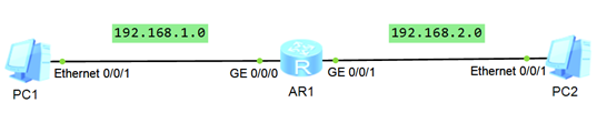
图-1
1.3 步骤
实现此案例需要按照如下步骤进行。
1)利用PC1 ping PC2 ,在 Ge0/0/0抓包,抓到Echo报文,如图-2所示
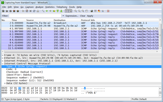
图-2
2)抓到Echo Reply报文,如图-3所示
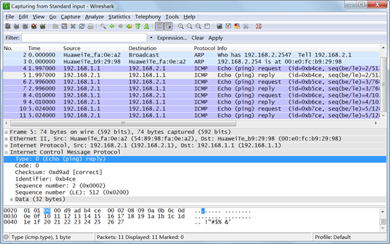
图-3
2 案例:ARP协议抓包分析
2.1 问题
- 使用eNSP搭建实验环境,
- 在PC1接口开始抓包,
- 在PC1上ping PC2
- 抓包分析ARP协议、查看ARP缓存表
2.2 方案
使用eNSP搭建实验环境,如图-4所示
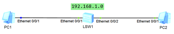
图-4
2.3 步骤
实现此案例需要按照如下步骤进行。
1)在PC1的端口抓包,并使用 PC1 ping PC2,抓到ARP请求包,如图-5所示
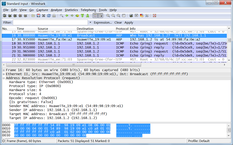
图-5
2)抓到ARP回应包,如图-6所示
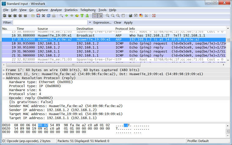
图-6
3)在PC1上查看ARP缓存表,如图-7所示
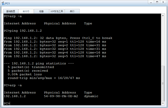
图-7
3 案例:认识路由表
3.1 问题
- 使用eNSP搭建实验环境,如图配置IP地址
- 查看路由器的路由表条目信息
3.2 方案
使用eNSP搭建实验环境,如图-8所示
/
图-8
3.3 步骤
1)配置PC的IP地址,如图-9所示。
/
/
图-9
2)配置路由器的IP地址,并查看路由表
<Huawei>system-view
[Huawei]sysname R1
[R1]interface GigabitEthernet 0/0/1
[R1-GigabitEthernet0/0/1]ip address  192.168.1.254 24
[R1-GigabitEthernet0/0/1]quit

[R1]interface GigabitEthernet 0/0/2
[R1-GigabitEthernet0/0/2]ip add 192.168.2.254 24
[R1-GigabitEthernet0/0/2]quit

[R1]display ip routing-table                            //查看路由器的全部路由表
Route Flags: R - relay, D - download to fib
------------------------------------------------------------------------------
Routing Tables: Public
Destinations : 10       Routes : 10
Destination/Mask  Proto   Pre  Cost Flags NextHop         Interface
  192.168.1.0/24   Direct   0    0    D    192.168.1.254   GigabitEthernet0/0/1
  192.168.2.0/24   Direct   0    0    D    192.168.2.254   GigabitEthernet0/0/2
(其他非关键路由条目,已经省略)
[R1]display ip routing-table  192.168.2.1      //查看去往 192.168.2.1使用的路由
Route Flags: R - relay, D - download to fib
------------------------------------------------------------------------------
Routing Table : Public
Destination/Mask  Proto   Pre  Cost  Flags NextHop         Interface
192.168.2.0/24  Direct  0    0      D     192.168.2.254   GigabitEthernet0/0/2

[R1]display ip routing-table  192.168.1.1      //查看去往 192.168.1.1使用的路由
Route Flags: R - relay, D - download to fib
------------------------------------------------------------------------------
Routing Table : Public
Destination/Mask  Proto   Pre  Cost  Flags NextHop         Interface
192.168.1.0/24  Direct  0    0      D     192.168.1.254   GigabitEthernet0/0/1
4 案例:配置静态路由
4.1 问题
- 所有网段均使用 192.168.x.0/24
- 为所有设备配置相应的IP地址
- 为每台路由器添加相应的路由条目
- 确保全网设备之间互通
4.2 方案
使用eNSP搭建实验环境,如图-11所示
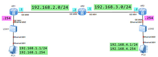
图-11
4.3 步骤
1)如图配置PC1/2的IP地址
如图配置R1、R2和R3的接口IP地址
2)在R1上添加静态路由条目
[R1]ip route-static 192.168.4.0 24 192.168.2.2
3)在R2上添加静态路由条目
[R2]ip route-static 192.168.1.0  24  192.168.2.1
[R2]ip route-static 192.168.4.0  24  192.168.3.2
4)在R3 上添加静态路由条目
[R3]ip route-static 192.168.1.0 24 192.168.3.1
5)在 PC1上 ping PC2 的IP地址,结果是:互通。
5 案例:路由网络综合配置
5.1 问题
配置接口IP地址,并通过静态路由实现全网互通
5.2 方案
使用eNSP搭建实验环境,如图-12所示。
/
图-12
5.3 步骤
1)如图配置PC1/2/3/4的IP地址
2)如图配置R1、R2、R3、R4的接口IP地址
3)在R1上添加静态路由条目
[R1]ip route-static 192.168.2.0  24  192.168.5.2
[R1]ip route-static 192.168.4.0  24  192.168.8.2
[R1]ip route-static 192.168.3.0  24  192.168.5.2
[R1]ip route-static 192.168.3.0  24  192.168.8.2
4)在R2上添加静态路由条目
[R2]ip route-static 192.168.1.0  24  192.168.5.1
[R2]ip route-static 192.168.3.0  24  192.168.6.1
[R2]ip route-static 192.168.4.0  24  192.168.5.1
[R2]ip route-static 192.168.4.0  24  192.168.6.1
5)在R3 上添加静态路由条目
[R3]ip route-static 192.168.2.0  24  192.168.6.2
[R3]ip route-static 192.168.4.0  24  192.168.7.2
[R3]ip route-static 192.168.1.0  24  192.168.6.2
[R3]ip route-static 192.168.1.0  24  192.168.7.2
6)在R4 上添加静态路由条目
[R4]ip route-static 192.168.1.0  24  192.168.8.1
[R4]ip route-static 192.168.3.0  24  192.168.7.1
[R4]ip route-static 192.168.2.0  24  192.168.8.1
[R4]ip route-static 192.168.2.0  24  192.168.7.1
7)在每个PC上通过 Ping命令,测试与其他 PC 的IP地址,结果是:互通。
6 案例:小型企业网络组网方案
6.1 问题
- 公司内部有3个部门:市场部、财务部、技术部
- 每个部门分别属于不同的网段,如图中所示
- 每个部门中存在2台终端设备,IP地址为 192.168.xx.1和 192.168.xx.2
- 每个终端设备的网关IP地址为:192.168.xx.254
- 合理配置IP地址和路由信息,确保不同的网段之间可以互相通信
- 为SW1配置IP地址:192.168.1.88/24,要求通过 telnet 方式远程管理 R1/2/3,用户名为 Tedu,密码为 NTD123@
6.2 方案
使用eNSP搭建实验环境,如图-13所示。
/
图-13
6.3 步骤
1)如图配置PC1-PC6的IP地址
2)如图配置R1、R2、R3的接口IP地址
3)在R1上配置静态路由
[R1]ip route-static 192.168.2.0   24  192.168.12.2
[R1]ip route-static 192.168.4.0   24  192.168.12.2
[R1]ip route-static 192.168.24.0  24  192.168.12.2
4)在R2上配置静态路由
[R2]ip route-static  192.168.1.0  24  192.168.12.1
[R2]ip route-static  192.168.4.0  24  192.168.24.3
5)在 R3 上配置静态路由
[R3]ip route-static  192.168.1.0   24  192.168.24.2
[R3]ip route-static  192.168.2.0   24  192.168.24.2
[R3]ip route-static  192.168.12.0  24  192.168.24.2
6)在R1/R2/R3上配置 telnet功能
aaa
local-user Tedu password cipher NTD123@
local-user Tedu service-type telnet
quit

user-interface  vty  0  4
authentication-mode  aaa
quit
7)配置 SW1 的IP地址和静态路由
interface vlanif 1
ip address 192.168.1.88 24
quit

ip route-static 192.168.2.0 24 192.168.1.254
ip route-static 192.168.4.0 24 192.168.1.254
8)在 SW1 进行 telnet 测试,登录 R1/R2/R3 ,以远程登录 R1 为例。
<SW1>telnet 192.168.1.254                      // 在SW1的用户视图使用远程登录
Trying 192.168.1.254 ...
Press CTRL+K to abort
Connected to 192.168.1.254 ...

Login authentication
Username:Tedu                                   //  输入用户名
Password:                                       //  输入密码
<R1>                                             //  远程登录成功